
How to Place GCPs for Drones Topographic Surveying
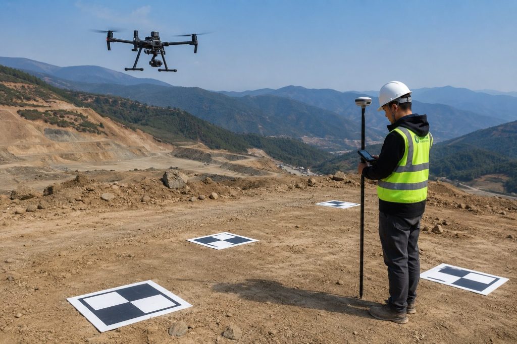
Ground Control Points (GCPs) are a crucial element in determining the final “absolute accuracy” of drone topographic survey. Even when using RTK/PPK UAV systems, the results may still exhibit overall offset or elevation distortion without a proper GCP layout.
According to the ASPRS Positional Accuracy Standards (2014/2023), the accuracy of surveying results must be based on the RMSE calculated from independent checkpoints, rather than solely relying on the internal errors optimized from control points. This means that GCPs are not only used for modeling constraints but also serve as anchor points for the spatial coordinate system.
Table of Contents
The Core Role of GCP in Drone Topographic Survey
In photogrammetry, UAV imagery is used to generate point clouds and orthophotos through feature matching, but this process is essentially a “relative model.” The role of Georeferenced Conformance (GCP) is to bind this model to the real geographic coordinate system.
DJI Terra’s official documentation also points out that while RTK/PPK can improve positioning accuracy, GCP is still needed for absolute correction when high-precision georeferenced reference is required.
3 Key Preparations before GCP Deployment
During project implementation, many surveying errors do not occur in the later stages of modeling, but are already present before the deployment of GCPs (Government Control Points). According to the USGS Photogrammetry Guidance, the rationality of control point layout depends on the advance assessment of the survey area’s terrain, flight parameters, and target design. If these three aspects are insufficiently prepared, even increasing the number of control points will not effectively improve the accuracy of the final results.
Terrain Analysis
Topographical structure determines the locations where model errors are most likely to occur. The more pronounced the topographic relief, the more prone the photogrammetric model is to local stretching or compression in the vertical direction. If control points cannot cover these areas of elevation change, the subsequently generated DEM and contour lines will often show significant deviations.
In practical topographical surveying, the following logic can be used to determine the source:
| Terrain Type | Typical Scenarios | GCP Placement Strategy | Why This Works | What Happens If You Don’t |
| Flat Areas | Farmland, industrial parks, airport runways, large warehouse areas | Place GCPs at the four corners + center | Elevation changes are minimal, so GCPs mainly stabilize overall coordinates and boundary accuracy | The model may show slight overall shift and reduced edge accuracy |
| Gentle Slopes or Rolling Terrain | Hilly areas, construction zones, earthwork preparation areas, road slopes | Add GCPs at hilltops, slope bottoms, and terrain transition points | This constrains elevation changes and reduces local error accumulation | Slopes may appear stretched, compressed, or locally distorted |
| Mountainous or Mining Areas | Open-pit mines, canyon terrain, mountain roads, complex terraced slopes | Place GCPs on each major slope surface, especially at ridge tops, valley bottoms, and platforms | Large elevation differences and shadowing require independent spatial control for each surface | Slope deformation and significant DEM elevation errors may occur |
The more complex the terrain, the more GCP should cover “change points” rather than mechanically increasing the number of machines.
Determine Flight Parameters
Many people are accustomed to flying the drone first and then deciding on the control point accuracy requirements, but this is actually the reverse. In drone topographic survey, flight altitude directly affects the Ground Sample Distance (GSD), which in turn determines the theoretical resolution of the model.
For example:
- At a flight altitude of 100m, the common GSD in RGB aerial surveys is approximately 2–3 cm.
- At a flight altitude of 50m, it can be reduced to 1–1.5 cm.
A smaller GSD means more refined image recognition, but it also requires smaller GCP measurement errors. If your measured GCP error reaches 3cm, but the theoretical image resolution has reached 1cm, then the control points themselves will become a source of error.
Furthermore, overlap also affects control point requirements:
- High overlap (above 80/70): The model is stable, and the number of points can be appropriately reduced.
- Low overlap (below 70/60): The model is less rigid, requiring more GCP constraints.
The accuracy of the GCP should be at least 2–3 times better than the image GSD; otherwise, the advantages of high-resolution imagery cannot be fully utilized. Therefore, before setting up control points, the flight altitude, camera parameters, target GSD, and forward and lateral overlap rate must be determined. Only in this way can the required level of accuracy for the control points be determined.
Choose A Suitable Target
Control point accuracy depends not only on RTK measurements but also on the accuracy of the post-processing software in identifying the target center.
According to Pix4D’s official recommendations, the target should occupy at least 8–12 pixels in width within the image for the software to stably identify its center position.
If the target is too small, it will lead to:
- Center identification offset
- Increased manual annotation error
- Bundle Adjustment constraint failure
For example:
If the project’s GSD is 2cm, a target width of at least 20–30cm is recommended;
If the GSD reaches 1cm, a width of 40cm or more is recommended for greater stability.
Additionally, the target must meet three conditions:
| Requirement | Best Practice | Risk if Ignored |
| High Contrast | Use black-and-white targets | Poor center detection |
| Secure Placement | Fix targets firmly in place | Invalid control data |
| No Glare or Shadows | Keep targets clearly visible | Reduced positioning accuracy |
A target that can be stably identified is more valuable than a point with higher theoretical coordinates but which cannot be identified.
GCP Deployment Core Principles
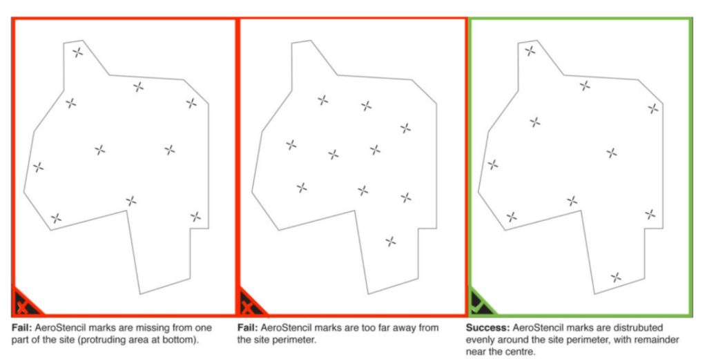
Principle 1: Boundary Priority + Uniform Distribution
Control points should prioritize covering boundary areas to minimize spatial distortion.
Recommended layout:
- Control points must be placed at the four corners.
- Auxiliary control points should be placed in the center.
- Avoid concentrating control points in a single area.
Principle 2: Cover Areas of Elevation Change
The USGS points out that topographic variation is a significant source of DEM error. In practice, the following should be done:
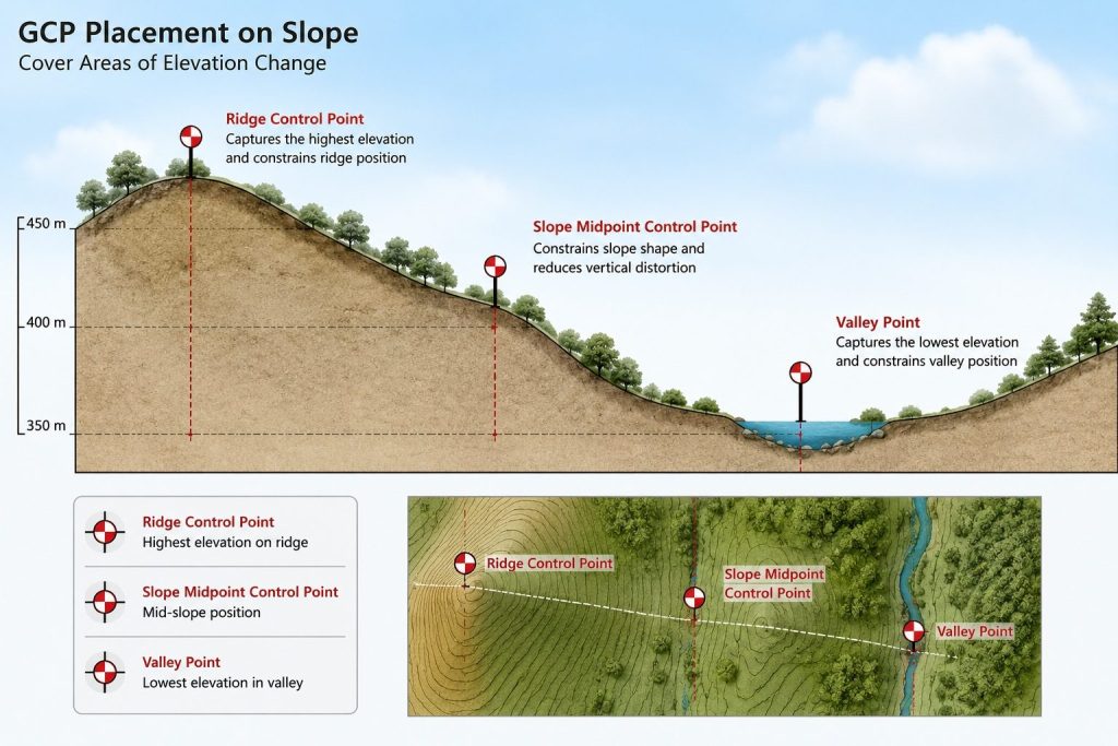
- Control points should be established on slopes at least once.
- Elevation difference areas must be controlled independently.
- Avoid “planar point layout”.
Principle 3: Checkpoints Must Be Set
According to industry standards, 20%–30% of the points should be used as independent checkpoints, not involved in model optimization, but used to calculate RMSE.
This avoids the problem of “humanly optimizing accuracy” and makes the results closer to the true error.
Principle 4: Quantity Matches Project Size
Industry Software (Pix4D / Metashape) Recommendations:
- Small Scale (<50ha): 5–8 units
- Medium Scale (50–200ha): 8–15 units
- Large Scale: Zonal Control
Accuracy Influence Mechanism
In drone topographic survey, the role of Geomatics Compass (GCP) is not only to provide coordinates, but more importantly, to spatially constrain the overall model through bundle adjustment in photogrammetry.
UAV imagery initially generates a relative model, which can only reconstruct the terrain morphology, but may contain overall drift, scale errors, or elevation shifts. The addition of GCP provides a true coordinate reference for the model, helping the software correct position, orientation, and scale during the adjustment process, ensuring the results are accurately aligned with the real geographic coordinate system.
Mapping accuracy is typically assessed using Reliability and Sequence of Surveys (RMSE), and must be calculated based on independent checkpoints, not control points involved in the optimization.
Common industry-standard accuracy targets are typically:
- Horizontal error: 2–5 cm
- Elevation error: 5–10 cm
It’s important to note that even when using RTK or PPK drones, if GCPs (Gatekeeper Points) are concentrated in the center of the survey area, or if boundaries and areas of elevation change are ignored, the model may still exhibit edge stretching or localized elevation distortion.
In short:
The number of GCPs determines the coverage area, while their placement determines whether the error is truly controllable.
This is why, in high-quality topographical surveying, the placement of control points is more important than simply increasing their number.
Common Mistakes
In drone topographic survey, incorrect control point placement is often more detrimental to final accuracy than an insufficient number of points. The following problems are the most common and most likely to lead to biased results:
- GCPs concentrated in the central region: lack of boundary constraints, prone to edge stretching or overall model drift.
- Ignoring areas of elevation change: In slopes, mining areas, or undulating terrain, the lack of elevation control points can lead to local distortion of the DEM.
- Misconception that RTK can completely replace GCPs: RTK improves initial positioning accuracy but cannot completely eliminate absolute coordinate errors.
- Target size mismatch with GSD: Targets that are too small can affect the software’s ability to identify the center point, reducing control accuracy.
- No independent checkpoints: RMSE cannot be truly verified, resulting in unreliable accuracy results.
- GCPs not securely fixed: Wind, vehicle vibration, or ground movement can cause control points to fail.
In short, the key to high-quality topographical surveying is not “setting up more points,” but avoiding these fundamental errors and ensuring that each control point truly participates in model constraints.